Product Details:
Payment & Shipping Terms:
|
| Output Signal: | 4-20mA/HART | Power Supply: | 24V DC |
|---|---|---|---|
| Operating Temperature: | -40 To +140C | Skype: | Summer.cao39 |
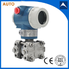
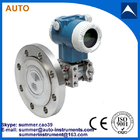
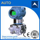
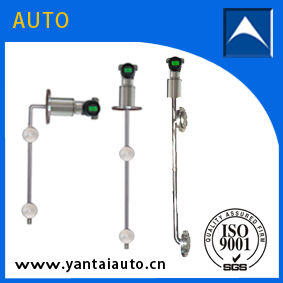
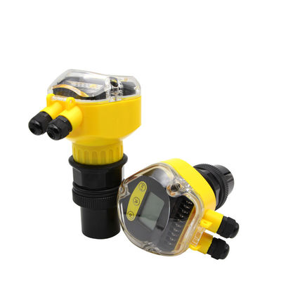
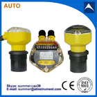
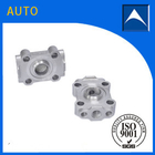
| Name: | Differential Pressure Transmitter |
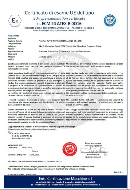
AT3051 Differential Pressure Transmitter with reasonable price Made In China
![]()
Function Parameters:
1. Applicable Object: Liquid, gas, steam
2. Measuring range: 0~0.1KPa to 0~40MPa
3. Output Signal: 4~20mA DC
4. Power Source: 12~45V DC, 24V DC on average
5. Load Characteristic: Depend on power resource. The relation of RL and VS is: RL≤50 (VS-12)
6. Indicating Gauge: Multiple parameters and multiple ways LCD indicate header
7. EX-proof: a. Exd Type ExdllCT6 b. intrinsic safety Type ExidllCT4
8. Range and Zero Point: Outer continually adjustable
9. Positive And Negative Shift: When zero passes positive or negative shift, upper limit and lower limit of
measuring range cannot exceed 100% of upper limit. The maximum positive shift is 500% that of minimum
adjustment range; the maximum negative shift range is 600% that of minimum adjustment range.
10. Temp Range: Working temperature range of amplifier: -29~+93 °c (LT type: -25~+70°c)
11. Filling silicone oil measuring element: -40~+104°C
12. Filling High Temperature Oil to Flange Transmitter : +15~+315°C
13. Common Silicone Oil: -40~+149°C
14. Static Pressure: 4, 10, 25, 32MPa
15. Humidity: relative humidity 0~100%
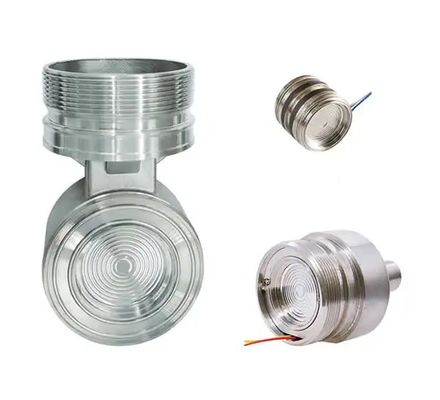
16. Volume Absorb Quantity: <0.16cm3
![]()
Differential Pressure Transmitter MainTechnical Parameters:
|
Accuracy: |
±0.1%, ±0.075% |
|
Dead zone: |
No (≤0.1%) |
|
Stability: |
Less than the absolute value of basic error of maximum range within 6 months. |
|
Vibration Effect: |
With 200HZ vibration frequency and error that of ±0.05%/g upper limit of measuring range in arbitrary axis |
|
Power Source Effect: |
<0.005%/V output range |
|
Load Effect: |
No load effect under stable power source |
![]()
Ording information sheet
|
Name |
Specification code |
Explanation |
||
|
AT3051DP AT3051DR |
|
Differential Pressure Transmitter micro-Differential Pressure Transmitter |
||
|
|
2 |
(0.0013-0.013)bar |
||
|
3 |
(0.013-0.075)bar |
|||
|
4 |
(0.062-0.374)bar |
|||
|
5 |
(0.31-1.868)bar |
|||
|
6 |
(1.17-6.9)bar |
|||
|
7 |
(3.45-20.68)bar |
|||
|
8 |
(11.7-68.90)bar |
|||
|
Output Signal |
E |
analog type 4-20mA |
||
|
S |
4-20mA, HART Protocol Digital Communication |
|||
|
Wetted Parts Material |
|
Flange/Joint |
Exhaust/Drain Valve |
Diaphragm |
|
22 |
Stainless Steel |
Stainless Steel |
316L Stainless Steel |
|
|
23 |
Hastelloy C-276 |
|||
|
24 |
Tantalum |
|||
|
Mounting Bracket |
B1 |
Tube-type Curved Bracket (Tube ODΦ50~Φ60) |
||
|
B2 |
Board- type Curved Bracket |
|||
|
B3 |
Tube-type Straight Bracket (Tube ODΦ50~Φ60) |
|||
|
Display Header (optional) |
M2 |
Linear Pointer Header (0~100% scale) |
||
|
M3 |
Square Root Instruction Header(0~100% scale) |
|||
|
M4 |
LCD Header(0~100% linear display) |
|||
|
Process Flange |
D |
The liquid discharge / exhaust at the back |
||
|
D1 |
The liquid discharge / exhaust at the side top |
|||
|
D2 |
The liquid discharge / exhaust at the side bottom |
|||
|
Flange Joint |
J |
“D-shaped” Joint with “ M20*1.5” External thread |
||
|
|
N |
Joint with 1/2-14NPT taper pipe thread waist type |
||
![]()
Factory workshop:
![]()
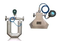
Installation:
![]()
![]()
Package:
![]()
Contact me:
![]()
| Factory Address:No.340 Changjiang Road, ETDZ,Yantai,Shandong,China | |
| Sales office:No.3 Hengshan Road, ETDZ,Yantai,Shandong,China | |
| +86--18906383510 | |
| summer@atinstruments.com | |